





 Landscape
GPS Drifting: The Physics Behind Phantom Movements and How Modern GPS Tracker Reduce It?
Admin 2026-04-17 497
Have you ever encountered a scene like this on a monitoring platform: a delivery truck, clearly parked right outside the company building, yet its trajectory shows it "strolling" down the adjacent block; an elderly person resting at home, yet their location marker appears to have drifted across the river; or a batch of goods stored in a warehouse, triggering a system alert that they are slowly moving?
This is neither a device malfunction nor a system bug; rather, it is a phenomenon inherent to GPS technology that cannot be entirely eliminated—GPS drift.
As an over 10 years R&D manufacturer who works with all kind of GPS tracking devices, I will unveil the physical nature of GPS drift, explain why it occurs, and reveal the technical strategies modern trackers employ to render this drift "acceptable."
1. What is GPS Drift?
GPS drift refers to the discrepancy between the position calculated by a GPS receiver and the actual geographical location; it manifests as coordinates continuing to shift while the device remains stationary, or as a recorded movement trajectory that does not align with the true path.
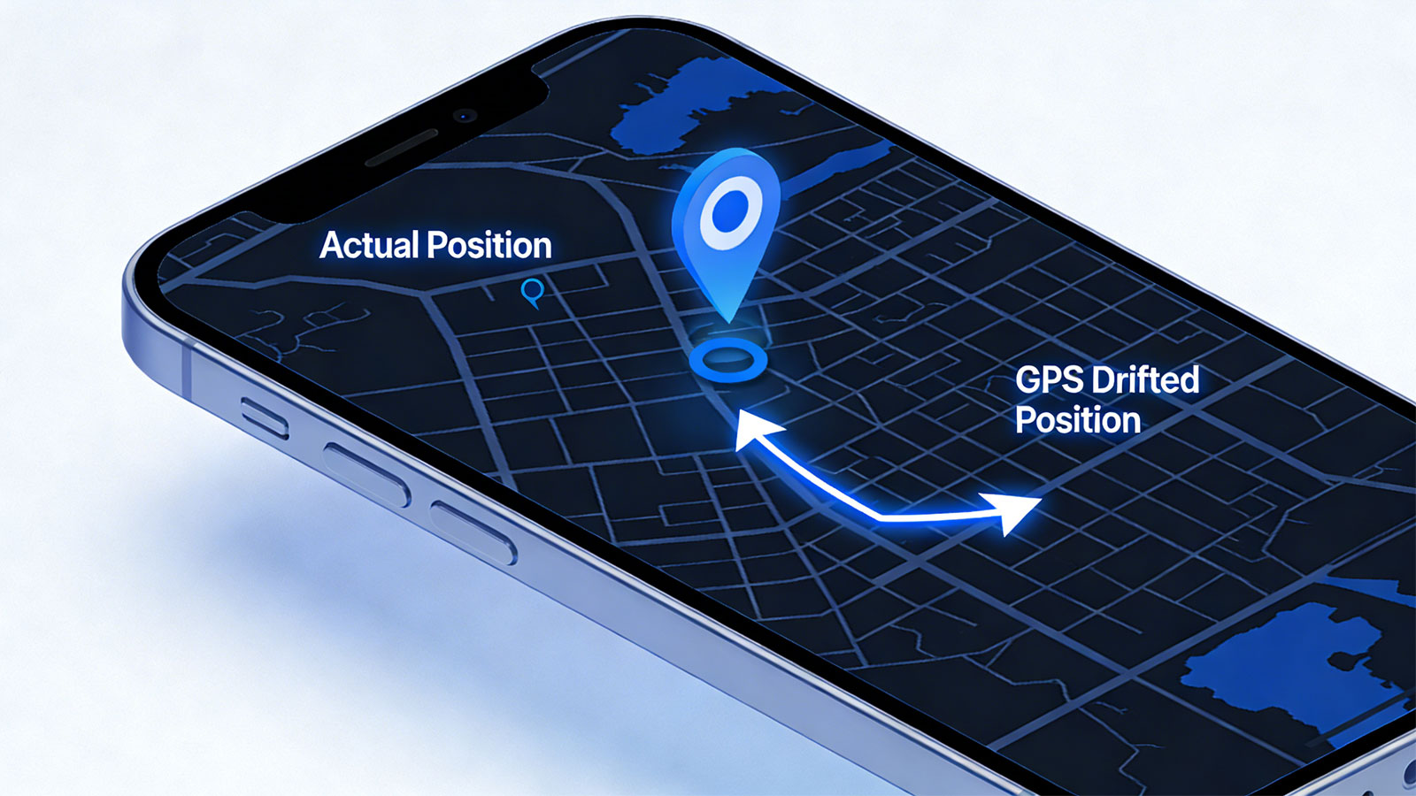
1.1 Typical Manifestations
| Type | Phenomena | Business Impact |
| Static Drift | The personal or vehicle is stopped or parked in a lot, yet its icon on the map appears to be slowly drifting or jumping around. | Generation of spurious mileage (e.g., the system records over ten kilometers of travel even though the vehicle remained stationary) |
| Dynamic Drift | The recorded travel trajectory deviates from the actual road, appearing as a jagged, sawtooth-like path. | Distorted route playback, inaccurate mileage calculations, and disputes regarding toll charges. |
| Jump Point Drift | The reported location suddenly jumps several hundred meters away, only to jump back again. | False triggering of alarms (e.g., erroneous "Geofence Exit" alerts). |
1.2 Quantitative Metrics for Drift
In technical terminology, drift is typically measured using the following metrics:
| Indicator | Definition | Typical Value (Open Field) |
| CEP (Circular Error Probable) | 50% of positioning points fall within this circle | 2-3 meters |
| 95% Error Circle | 95% of positioning points fall within this circle | 5-8 meters |
| Maximum Error | Deviation under extreme conditions | 10-30 meters (Urban Environment) |
2. The Physics Behind Drift: Why Does GPS "Drift"?
The root cause of GPS drift lies in the various forms of interference and error that occur during the signal propagation process. These errors accumulate, causing the calculated position to deviate from the actual location.
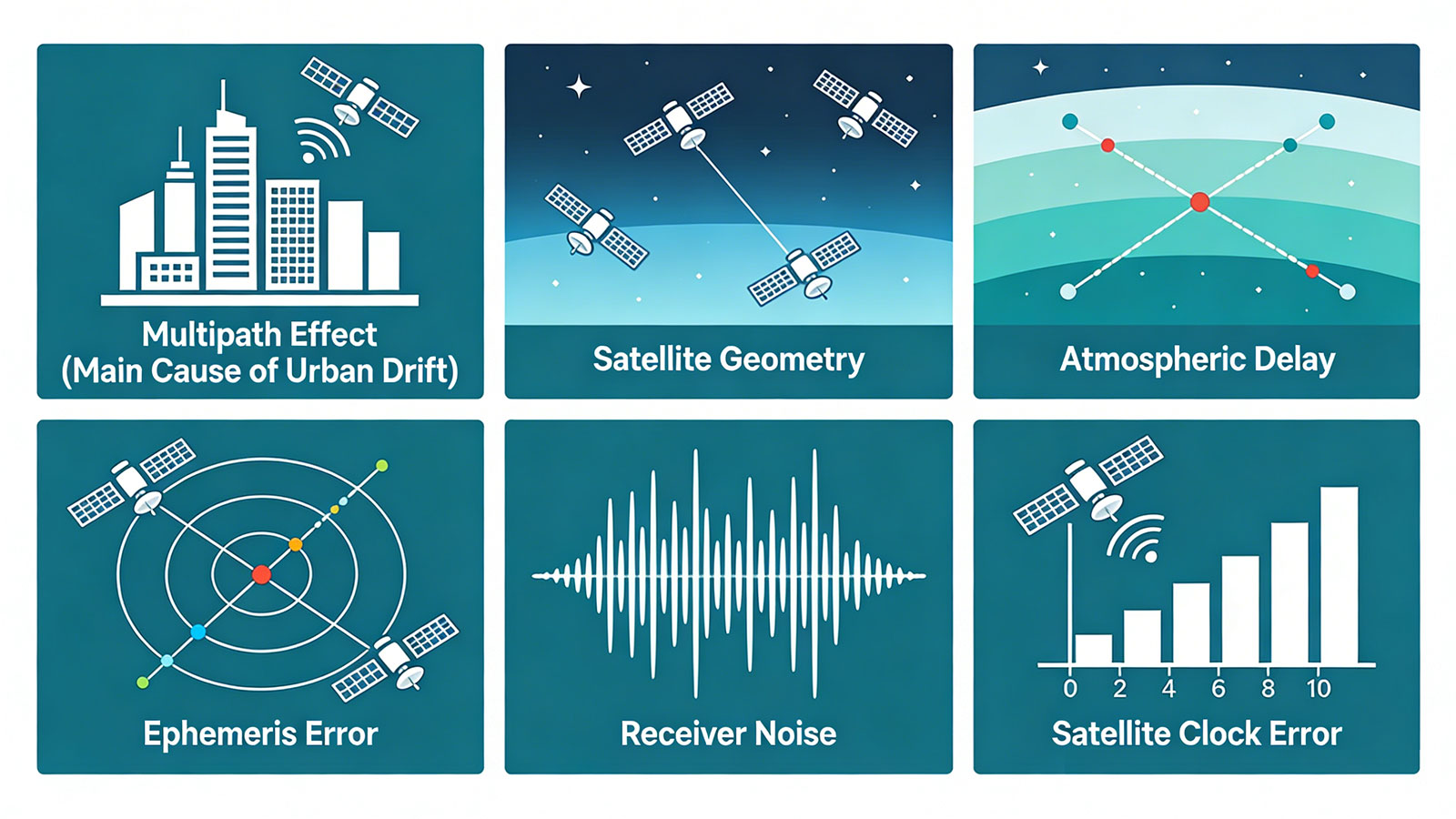
2.1 Multipath Effect (The Primary Cause of "Urban Drift")
This constitutes the single largest source of positional drift in urban environments.
Principle: When GPS signals propagate through an environment containing reflective surfaces—such as high-rise buildings, bodies of water, or metal structures—they undergo multiple reflections before finally reaching the receiver. The receiver is unable to distinguish between direct signals and reflected signals; it erroneously interprets the reflected signals as having traveled a longer path, thereby calculating an incorrect position.
Analogy: This is similar to hearing an echo in a valley—the "sound" you perceive arrives from multiple directions, making it difficult to pinpoint the true location of the sound source.
Impact Severity:
Open Terrain: Negligible
Urban Streets: 5–15 meters of deviation
Urban Canyons (High-rise Areas): 10–50 meters of deviation; in severe cases, this can exceed 100 meters.
Typical Scenarios:
A vehicle driving beneath an elevated highway, where its plotted trajectory jumps to the side of the bridge.
Parking next to a building with a glass curtain wall, causing the reported position to constantly fluctuate.
Driving along a riverside road, where the reported position drifts across to the opposite bank of the river.
2.2 Satellite Geometric Distribution
Principle: Even if the number of available satellites is sufficient, their spatial distribution is of critical importance. When satellites are clustered within a single region of the sky, the resulting position fix resembles "pinching a ball with just two fingers"—highly accurate in the fore-and-aft direction, but prone to drifting laterally.
Technical Metric: DOP (Dilution of Precision)
HDOP < 1: Excellent
HDOP 1–2: Good
HDOP 2–5: Moderate
HDOP > 5: Poor
Simplified Analogy: If four satellites are distributed evenly across the four cardinal directions—East, South, West, and North—the position fix is effectively "framed" in the center, yielding maximum accuracy. Conversely, if four satellites are clustered tightly in the southeast, the position fix is akin to being "pushed from one side," making it susceptible to drifting toward the northwest.
2.3 Atmospheric Delay
Ionospheric Delay: When GPS signals traverse the ionosphere—located at an altitude of 60 to 1000 kilometers above the ground—their propagation speed slows down. The magnitude of this delay depends on solar activity, time of day (day vs. night), and geographic location.
Error Contribution: 5–15 meters (daytime), 2–5 meters (nighttime).
Tropospheric Delay: Water vapor and dry air within the troposphere—located at an altitude of 0 to 40 kilometers above the ground—also delay signal propagation.
Error Contribution: 2–5 meters (depending on humidity and elevation angle).
2.4 Satellite Ephemeris Errors
GPS satellites do not orbit along absolutely precise trajectories. Influenced by factors such as the Earth's non-uniform gravitational field and solar radiation pressure, satellites gradually drift away from their predicted orbits. Although ground control systems update the ephemeris daily, minute errors still persist.
Contributing Error: Approximately 1–2 meters
2.5 Receiver Noise
All electronic components generate thermal noise, which affects the precision of signal processing. Lower-quality receivers exhibit higher noise levels and more pronounced drift.
Contributing Error: 0.5–2 meters (depending on receiver quality)
2.6 Satellite Clock Errors
Satellites are equipped with atomic clocks of extremely high precision; however, they still experience minute drift. Ground stations monitor and broadcast clock correction parameters, yet residual errors remain even after correction.
Contributing Error: Approximately 1–2 meters
3. Why Is It Impossible to Completely Eliminate GPS Drift?
Once the sources of drift are understood, it is not difficult to see why it cannot be "eliminated"—these limitations represent the boundaries of physics and technology.

3.1 Physical Limitations
Finite Speed of Light: In signal propagation time measurements, an error of 1 nanosecond (one-billionth of a second) corresponds to a distance error of approximately 30 centimeters. Any timing error translates directly into a positional error.
Unpredictable Atmosphere: The ionosphere and troposphere are dynamic environments; no model can completely eliminate their effects.
Signal Wavelength Limitations: The GPS signal wavelength is 19 centimeters (L1 band); theoretically, it is impossible to achieve a positioning accuracy that exceeds this wavelength limit.
3.2 Technical Limitations
Civilian Signal Accuracy: Although the U.S. government lifted the SA (Selective Availability) policy in 2000, an inherent difference in accuracy between civilian and military signals persists.
Single-Frequency Reception Limitations: Most consumer-grade devices utilize single-frequency (L1) reception and, unlike dual-frequency receivers, cannot directly measure and compensate for ionospheric delays.
Size and Power Consumption Constraints: High-precision positioning requires larger antennas, greater computational power, and higher energy consumption—requirements that conflict with the demand for thin, lightweight, and long-battery-life portable devices.
3.3 Environmental Limitations
Urban Canyons: In environments dominated by high-rise buildings, multipath effects cannot be completely eliminated.
Tree Canopy Obstruction: The moisture contained within tree foliage absorbs and scatters GPS signals.
Metal Structures: Metal objects—such as vehicles and shipping containers—can completely block signals or cause severe signal reflection.
4. How Do Modern GPS Trackers Reduce Drift?
While drift cannot be completely eliminated, it can be suppressed to within an acceptable range through systems engineering approaches.
4.1 Hardware-Level Optimization
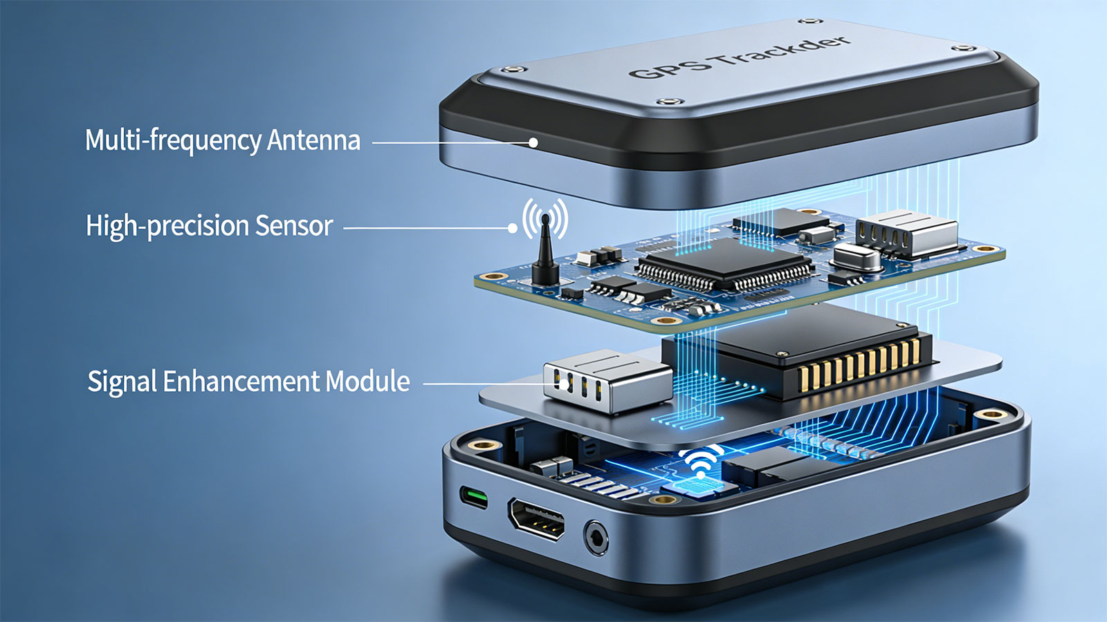
Multi-Constellation Reception
Simultaneous reception of GPS, BeiDou, GLONASS, and Galileo increases the number of available satellites by 40–60%, significantly improving satellite geometric distribution.
Effect: HDOP value reduced by 30–50%; drift minimized.
Implementation: Utilizes multi-constellation receiver chips—specifically, multi-mode solutions from manufacturers such as Qualcomm, ASR, and MTK.
High-Sensitivity Receiver
Acquisition Sensitivity: -148 dBm to -162 dBm
Tracking Sensitivity: -165 dBm to -167 dBm
It remains capable of locking onto a greater number of satellites even in weak-signal environments (such as under tree cover or in urban canyons), thereby reducing drift caused by an insufficient number of visible satellites.
Antenna Optimization
Right-Hand Circular Polarization Design: Better matches the polarization of GPS signals and suppresses reflected signals.
Ground Plane Design: Reduces multipath signals originating from below.
Active Antenna: Features a built-in LNA to compensate for feedline loss and improve the signal-to-noise ratio.
4.2 Algorithmic Optimization
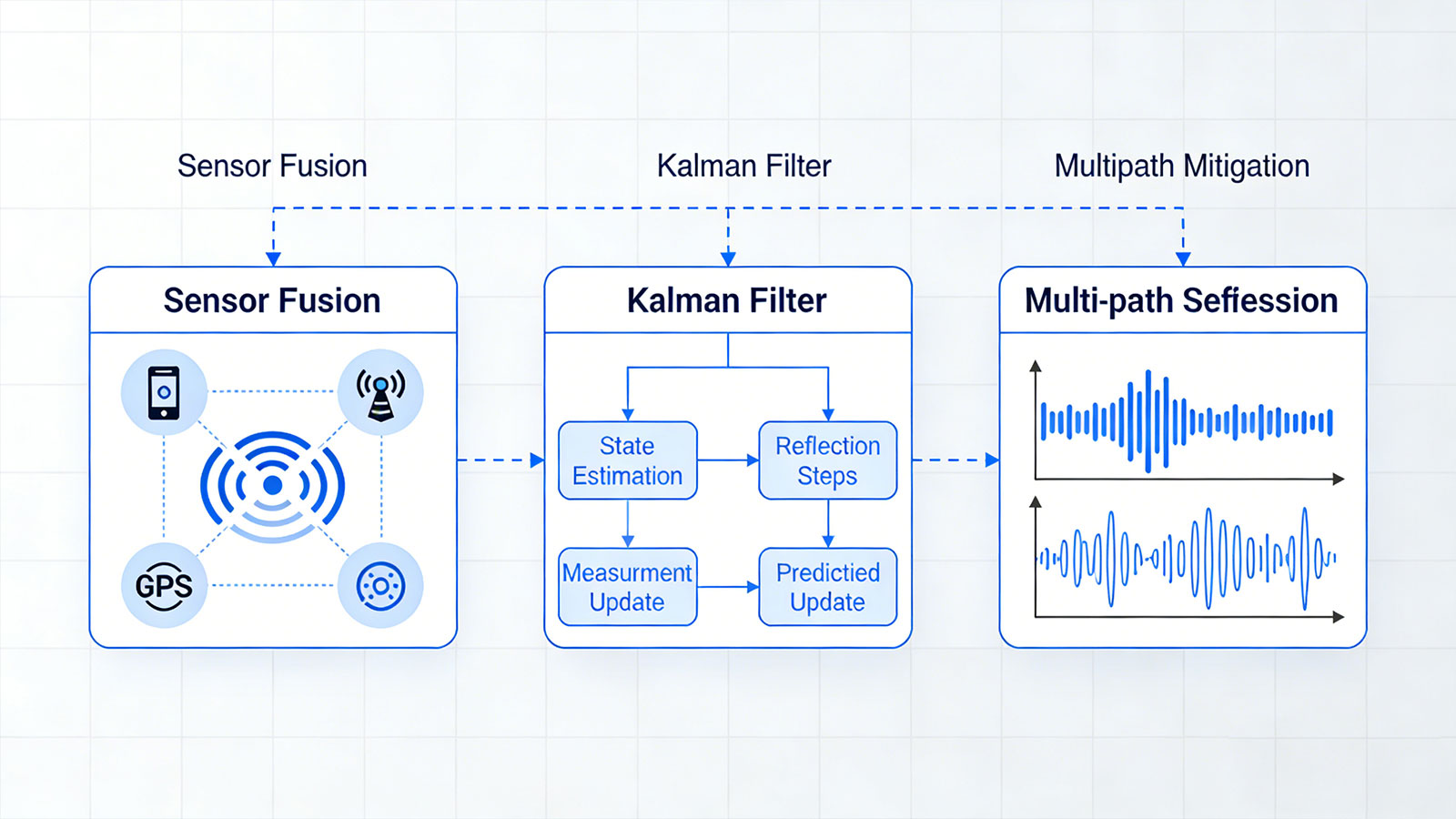
Kalman Filtering
Integrates historical trajectory data with current observations; it predicts the current position based on a motion model (constant velocity or constant acceleration) and performs a weighted average with GPS readings to effectively smooth out positional jumps.
Result: Static drift is reduced by over 70%, resulting in a smoother trajectory.
Implementation: Model parameters are adjusted according to the specific application scenario (vehicles, personnel, or assets).
Static Detection and Locking
Utilizes an accelerometer to determine whether the device is stationary. When stationary, the position is fixed—preventing any updates—thereby completely eliminating static drift.
Result: The reported position no longer "dances" or wanders while the device is parked.
Note: Requires a sufficiently sensitive motion sensor (capable of promptly waking the device upon detecting even minute vibrations).
Early Stop Mechanism
If fewer than three satellites are detected within a 3-second interval, GPS positioning is immediately terminated and switched to cell tower or Wi-Fi-based positioning to prevent unnecessary power consumption and erroneous data.
Effect: Prevents significant positional drift in areas with weak signal coverage.
Speed/Acceleration Threshold Filtering
Filters out implausible changes in position based on physical laws:
Maximum Speed Limit (e.g., assuming a vehicle speed does not exceed 200 km/h)
Maximum Acceleration Limit (e.g., preventing instantaneous "jumps" of 100 meters)
Direction Change Limit (e.g., preventing rapid, repetitive reversals in direction within a 30-second window)
Effect: Eliminates obvious, anomalous positional drift.
4.3 System-Level Optimization
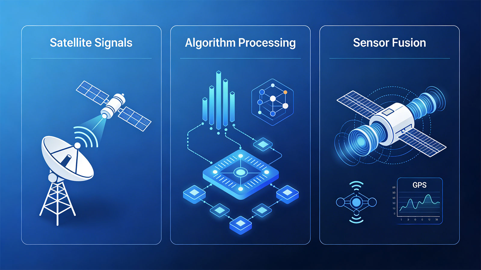
Multi-Source Fusion Positioning
| Technology | Accuracy | Applicable Scenarios | Fusion Strategy |
| GPS/GNSS | 2-10 meters | Open Outdoors | Primary Mode |
| Wi-Fi | 10-100 meters | Indoors / Urban Canyons | Activate When GPS Signal Is Weak |
| LBS | 100-3000 meters | Rough Positioning / Backup | When No Other Signals Are Present |
| Bluetooth | 1-5 meters | High-Precision Indoors | Requires Beacon Deployment |
Fusion Logic: Prioritize high-precision sources; automatically fall back to lower precision when accuracy is insufficient, ensuring that "having a position is always better than having no position." More advantages and disadvantages details of each kind of tracking methods check on: How Does GPS Tracker Works
Map Matching
"Snaps" raw trajectory points to the nearest road segments, eliminating off-road outliers caused by GPS drift.
Effect: The trajectory more accurately reflects the actual travel path.
Limitations: May result in incorrect matching during off-road driving.
Differential GPS (DGPS)
Utilizes a reference station at a known location to calculate error correction values, which are then transmitted to a mobile station via a cellular network.
Result: Accuracy is enhanced to the sub-meter level.
Application: Professional applications requiring extremely high precision (e.g., precision agriculture, engineering surveying).
5. Huaten Global's Engineering Practices
Across all our trackers, we reduce drift in the following ways:
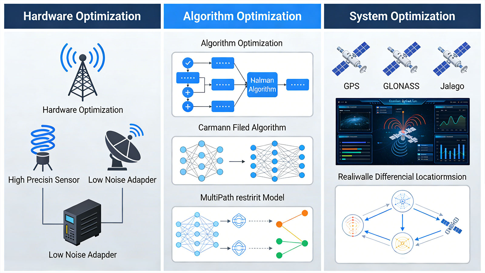
5.1 Hardware Layer
All models feature industrial-grade multi-constellation receiver chips (GPS + BeiDou + GLONASS).
Optimized antenna design, validated through passive antenna testing and active matching calibration.
High sensitivity, capable of locking onto a greater number of satellites even in weak-signal environments.
5.2 Firmware Layer
Intelligent Static Detection: Enforces a fixed position when stationary.
Early Termination Mechanism: Proactively abandons GPS and switches to alternative methods when signal quality is poor.
Adaptive Filtering: Dynamically adjusts filtering parameters based on motion state.
5.3 Platform Layer
Map Matching: Matches raw trajectory points to the nearest road segments.
Outlier Removal: Filters out obviously erroneous points based on velocity and directional logic.
Confidence Interval Display: Visualizes the probable range of the current location on the platform using a circle.
5.4 Measured Results
| Environment | Unoptimized | After Optimization | Magnitude of Improvement |
| Open Ground (Static) | 2–3 m CEP | 1.5–2 m CEP | 1.5–2 m CEP |
| Urban Canyon | 10–30 m CEP | 5–15 m CEP | 40-50% |
| Static Drift | 5–10 m drift | <2 m Drift | 80%+ |
| Trajectory Jump Points | 3–5 times per kilometer | <1 time per km | 70-80% |
6. As an Enterprise Client, What Can You Do?
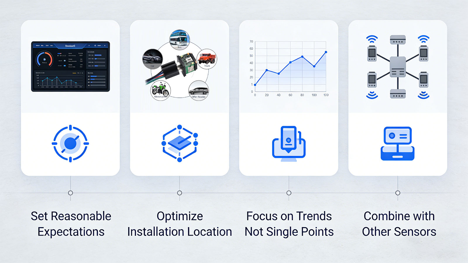
6.1 Set Realistic Expectations
Understand that GPS drift is the norm, not an anomaly. Clearly define the parameters and scope of positioning accuracy within your contract (e.g., "95% of data points fall within a 15-meter radius") to prevent disputes arising from misunderstandings.
6.2 Optimize Installation Locations
Vehicle Trackers: Ensure the antenna faces upward and is positioned away from metal obstructions (e.g., avoid concealing the device inside a metal trunk).
Personal Trackers: Avoid placing the device in deep pockets or within the inner compartments of backpacks; instead, position it as close as possible to the body's exterior.
Asset Trackers: Select a mounting location where the top of the device remains free of any metal covering.
6.3 Utilize Assisted Positioning
In indoor environments or densely built-up urban areas, enable Wi-Fi or Bluetooth-assisted positioning. Our platform automatically fuses data from multiple sources to enhance overall system reliability and usability.
6.4 Focus on Trends, Not Single Data Points
When making business decisions, prioritize the overall trajectory trends, dwell times, and zone entry/exit events, rather than fixating on the precise coordinates recorded at any single moment in time.
6.5 Integrate with Other Sensors
Leverage data from accelerometers, gyroscopes, door sensors, and similar devices to aid in status determination. For instance, even if minor GPS drift is detected, if the accelerometer indicates the object is stationary and the door sensors remain untriggered, you can confidently conclude—based on this combined data—that the vehicle has not, in fact, moved.
7. Conclusion
GPS drift is not a device defect, but rather an inevitable phenomenon of the physical world. Signals are subject to obstruction, reflection, and attenuation; satellite geometry varies in quality; and the atmosphere is in a constant state of flux.
More importantly, however: in the vast majority of commercial scenarios, this "imperfection" is both acceptable and manageable through systematic engineering approaches.
Huaten Global’s value does not lie in manufacturing a "zero-drift" GPS—a feat that is physically impossible. Our value lies in:
Possessing a deep understanding of the optimal balance point between the technical limitations of GPS and specific business requirements;
Controlling drift within a range that is acceptable for business operations through continuous optimization across hardware, algorithms, and system architecture;
Providing clients with transparent accuracy specifications and configuration tools, thereby enabling positioning data to truly serve as a foundation for business decision-making.
If you have more stringent requirements for drift suppression in specific scenarios, we invite you to contact our solutions team. We can arrange prototype testing to evaluate and optimize positioning performance within your actual deployment environment.
Search
Latest News
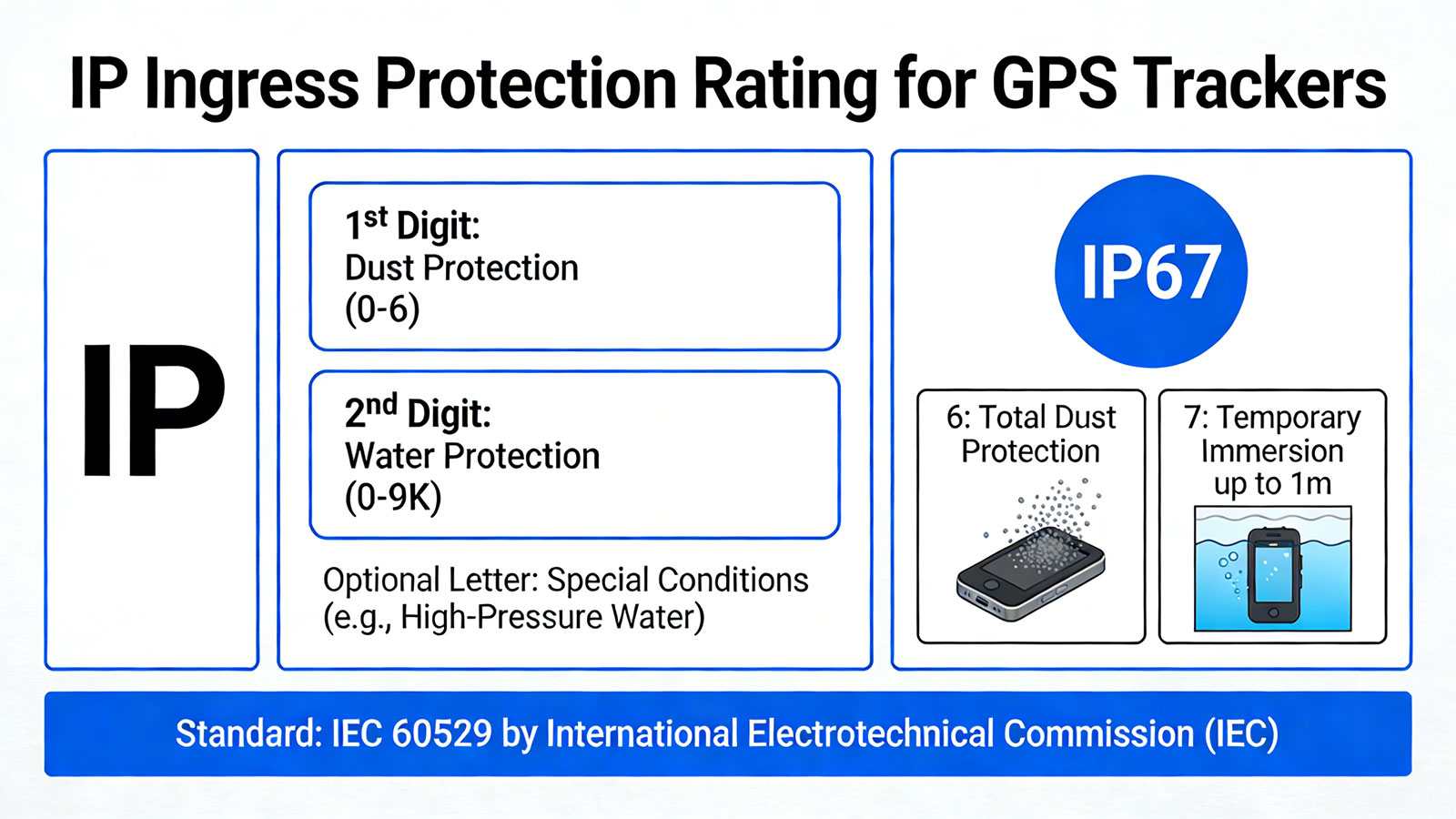
IP Protection Ratings is Not Permanent: Is Your GPS Tracking Device Truly Waterproof and Dustproof?

Is that Smartwatch Health Monitoring Medical Grade? - Focus on Trends, Not Medical Grade Disease Diagnosis Criteria
Battery Life Decoding: Seven Key Factors Affecting Your GPS Tracker Battery Duration
Is GPS Positioning Truly Real-Time? — The Truth About "Real-Time" GPS Tracking
Beyond Connectivity: What Your Tracker Can and Cannot Do When Cellular Networks Disappear?